By Minco Staff
Building a flex circuit is a complex task.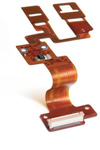 To make sure the project’s results match your expectations, it’s critical that the engineers working on your project understand your needs in detail. The package from which your circuit is built should consist of text and a variety of images showing multiple views and varying degrees of detail. Because the drawing for a flex circuit will be used both to estimate costs and to build the circuit, accuracy of this documentation matters a great deal. The drawing must address materials, physical description, and testing– CAD files alone are not sufficient for products in high reliability applications.
For best results, assemble the following materials before submitting the project to Minco:
Notes: Notes should cover required specifications, materials, testing, clarification of views, electrical requirements, plating and final finish, and assembly details. Notes are the best place to include amendments to specification requirements and part-specific quality expectations.
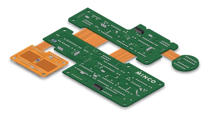
Circuit views: There should be at least one view that shows overall size, required dimensions, tolerance needs, established datums, and assembly needs. As complexity increases, multiple views may be needed. Because the circuits are made of flex materials, a simple tolerance block is frequently not sufficient for a part that is both producible and fully functional; geometric dimensioning and tolerancing (GD&T) is highly recommended. In general, views from the opposite side may be useful, and isometric views may be needed when forming is required.
Stackup: For complex circuits with multiple layers, isolated cutaways/exposures, and multiple stiffeners, a stackup view of materials helps clarify requirements. The stackup may detail required material thicknesses more effectively than an extended specification callout in the notes. Complex circuits may require cross sectional views if materials are non-uniform throughout the entire circuit.
Bill of Materials (BOM): If the circuit includes items such as components and connectors, a BOM should include these details. The BOM should either be part of the drawing or positively linked to the assembly drawing. For complex assemblies the best drawing packages include the bare PCB drawing, the assembly drawing, the CAD data, and the BOM itself. The BOM links these items along with components in one document. Proper revision control of all items, including CAD data, should also be in place in this documentation set.
Schematic: If a customer requires Minco to create CAD data for the circuit, then a schematic is required. The schematic should highlight any specific electrical needs and component callouts for the footprints. In many cases the details for materials and stackup cannot be finalized until the CAD data is completed, requiring close Engineer-to-Engineer (E2E™) contact between the end user and the CAD designer.
The best way to maximize the effectiveness of your flex project is to establish a relationship with a service provider with whom you can share clear and open communication lines. One of the reasons why Minco excels at providing flexible circuit solutions is our E2E focus, which allows us to collaborate with customers without unneeded layers of communication. Learn how Minco can help with your next flex project by downloading our Flex Circuit Design Guide, or if you’re ready to submit a project, refer to our downloadable New Flex Project worksheet.

