By Minco Staff
Minco has been building flex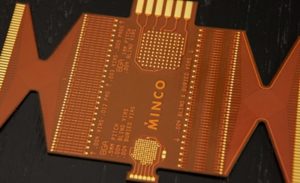 circuits for our customers for decades and we’ve encountered countless challenges along the way. Some of these pitfalls are encountered during the design process, others involve problems with documentation, and still others are mechanical issues with the design. Most of these ultimately impact our customers by costing time and resources.
The engineers of our Flex Circuit product family have assembled a list of the pitfalls they have most commonly encountered while working with customers.
Design Stage Pitfalls
Sometimes challenges present even before the design has been finalized. All too often we encounter these Design Stage pitfalls long after all the decisions have been made.
Charging Ahead Without Design Assistance: There are some flex users with long experience in designing and using flex, who have enough staff expertise to anticipate issues, design around them, and go it alone. Most companies do not fall into that category, however. Having experience designing rigid boards is a start but flex circuits are a “different animal” that have quite a few different concerns. Involving a trusted supplier is very important to head off the kind of issues that people have had with flex installations.
Considering Flex at the End of System Design, Rather than the Beginning: Designing an entire assembly, without any thought to the flex circuit needed at the end to connect all the elements, is likely to create a more expensive flex that could have issues. This approach can result in a larger-than-necessary circuit, which will result in higher costs. Excessively tight bends is also a possible result of not planning the flex-to-device connections when the design is not yet fixed.
Designs do not Utilize Design for Manufacturability (DFM) Practices: It is very common for designs to come in that have drawing requirements (or those from referenced specs) that are not supported by the CAD data. It is important to realize that there are many processes that will result in variations off the nominal. Additionally, flexible materials used to create flex circuits are much less stable than board materials, which needs to be accounted for in the design plan. Such factors as minimum line width/spacing, annular ring, border, etc. must all have manufacturing allowances built into the CAD design. Minco not only designs flex circuits, but we also prototype and manufacture them in-house, giving us the expertise to build manufacturability into the design.
Excessively Tight Tolerances: Every possible dimension on a flex circuit can be expected to have different tolerance capabilities, and often designs don’t reflect the realities of the material. For instance, stiffener size and location on the flex are frequently over toleranced. Hole pattern locations across a long flex area is another example, where flexing is inhibited by too many through-holes. A designer cannot know all the issues a manufacturer is facing but they should take a critical look at what their final assembly needs are and tolerance appropriately.
Documentation
A lot of problems can be avoided simply by keeping your documentation in order. The following are some documentation-related pitfalls we have encountered.
Not Creating a Comprehensive Drawing Package: Procuring a flex project takes more than just CAD data. A comprehensive drawing package is very important to tie together materials, thicknesses, tolerances, electrical concerns, specifications, testing, and to clarify any assembly issues. Flex circuits have become increasingly complex with cutaway areas and different via sets. Cross sectional views with thickness callouts can add a great deal of clarity. When in doubt add another view.
Improper Revision Control: All design elements, flex drawing, CAD data, assembly drawing, and BOM should be properly linked and under rev control. Even at the development stage there should be a clear indication of when there have been changes to the design elements as many are very difficult to notice.
Not Utilizing GD&T: Flex assemblies have a wide range of tolerance capabilities for many different dimensions, owing to the different processes and materials used. Trying to tolerance everything under a tolerance block is not an efficient way to control all elements such as hole size, hole positioning, outline, different termination areas, etc. GD&T offers the best means to bridge the gap between assembly needs and manufacturing capability.
Unrelated “Boilerplate” Notes: Many companies drop these notes in as a matter of standard procedure, and many are completely unrelated to the project or its quality needs. They add no value and can cause confusion at quoting, setup, and especially at first article inspection. Keep the drawing accurate!
Drawings/Designs Not Up to Passing a FAI: Requiring a first article inspection, even on legacy parts, has become common in recent years. In many if not most cases these designs will not pass the rigors of an AS-9102 review even though the product has functioned for years. Obsolete material and performance specs that are no longer used is one reason. Another is tolerances that were taken exception to, or should have been, years ago that did not get implemented on the drawing. To place an order for a legacy part with a PO-required FAI requires a pre-order drawing review with likely drawing updates. In some situations, it is wise for the flex producer to just start from scratch with a new NPI process.
Mechanical/Electrical Design Issues
A lot of problems we encounter can be attributed to circuit designers not understanding the strengths and weaknesses of flex.
Not considering number of flexes: The first question a flex designer must ask themselves is “how flexible must this circuit be?” This can vary widely from a dynamic installation on a print head (millions of cycles) to a circuit bent once on installation in a radio. If it is a dynamic design, you are likely limited to a thin 1-layer flex, certainly no more than 2 layers depending upon required cycles. Even if it is a static application, if the required bends are tight relative to flex thickness, there could be concerns with long term reliability if stress is not addressed.
Overspecifying the Circuit: It may be tempting to add every possible interconnection required into a single flex circuit, but there are reasons why this may not be the best approach. There are many different types of signals that can be integrated into a flex, everything from low voltage signals to power traces to EMI-shielded signals and high-speed signals with required reference planes. Satisfying the needs for all these type of circuit nets can lead to a flex that has many layers, is very thick, with poor flexibility. Some situations are best solved with multiple flex circuits. Others may be solved with reduced layers across areas that need to bend tightly. Often a rigid flex is a great solution.
Not Balancing Electrical/Mechanical Requirements: In trying to satisfy many of the needs (preferences?) of electrical designers there is frequently conflict with the mechanical desires of being thin and flexible enough to stand up to the application. High speed signals require thick substrates. High current layers may require thicker foil and adhesives. Sensitive signals might require shielding. These are all design issues to balance against the desire for a thin circuit with great flexibility.
Failing to Consider Cost Drivers: By far the two biggest cost drivers are number of layers and how many we can get on a panel. There are times when a slight shape adjustment can make a huge different in panel density, especially for larger circuits.
- Rigid flex: While a rigid flex can be and frequently is a great solution it does have a large cost impact over a plain flex of the same size and layer count. It is cheaper to add stiffeners to a multilayer flex, which is usually possible if all soldering is from one side.
- Complex via structures: These structures, such as blind and buried vias, require many more steps to create and bring with them different concerns.
- Multiple laminations: When there are cutaway layers for flexibility reasons costs will rise.
- Poor DFM: When the design offers poor manufacturing margins, costs will rise due to poor yields and increased inspection.
- High density traces/spaces on outside plated layers: This will affect yields negatively.
Make Minco Your Trusted Supplier
Finding a partner with vast experience, a proven supply chain, and the ability to guide a project from concept to manufacture all help in making the best solution. Involve Minco early on and let us help you save time and money on your next project. If you want to learn more, listen to our Engineer’s Corner podcast, in which our Flex Solutions engineers talk about pitfalls they have encountered.
